HolidayCoro Candy Cane - Part 2
In this section we will cover wiring the candy canes up and all the obstacles and pitfalls we came across. What looks like a simple project (and it really is) can get weighed down really quick
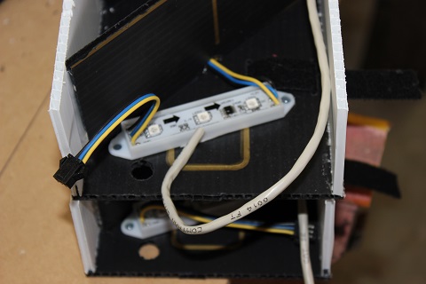
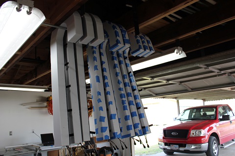
Now we start the wire-up process. Notice even though I advocate a better return wire, I had already done all the work with Cat5. I suggest using a 4 wire 18ga wire for the return that you will see later in this segment. The wires with the connector are the input and the Cat5 is the return (output) located at the bottom of the cane
|
We used a 4-pin waterproof connector for the whole project. These were bought from AliExpress.com. They were $1 a pair and included free shipping. The first order is cut off the connector and wire in the 4-pin connector. Notice I used the female connector on inputs and will use the male on outputs. Users Choice !! Wiring will be an individuals call. Since not all pixels and connectors are color coded the same. I used heat shrink on each indivisual wire and then over the whole connection. Make sure you run it THROUGH THE WHOLE FIRST, or else you have to do what I did when I forgot that is cut a slit to the hole and slip it into place.
|
Here is the INPUT connector wired and in place on the Candy Cane
|
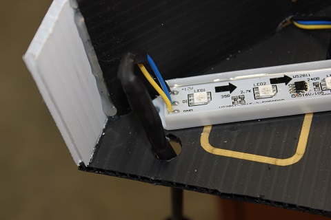
Now wire in the RETURN (output) wire in place. Again make sure you are through the hole before you solder together. Again I used heat shrink to seal and strengthen the joints.
|
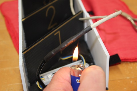
Here we see the last resort method of shrinking the tubing. Later in the project I came across a heat gun at Home Depot that was a return (I think someone thought it was a hair drier) becasue it ran slow. Well it doesnt. Funny thing is by the time I fishined haggling with the manager ... he just GAVE IT TO ME !!!
|
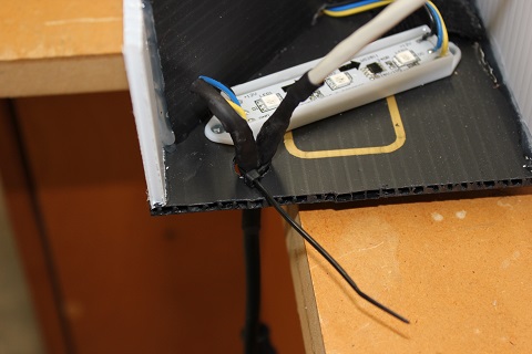
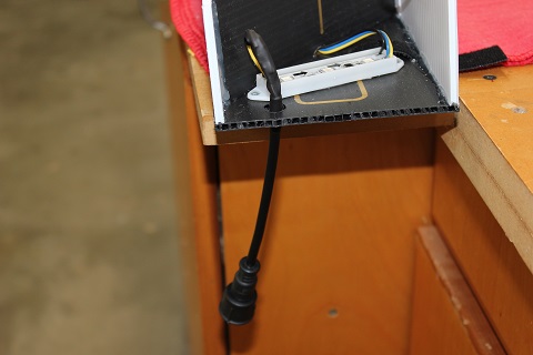
The tie wrap is almost a moot point but it keeps it from falling through the hole.
|
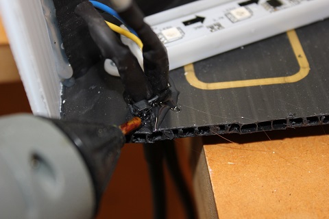
To help seal and strengthen (read as strain relief) the wires I just used a little hot glue and filled in the hole. This has worked well so far.
|
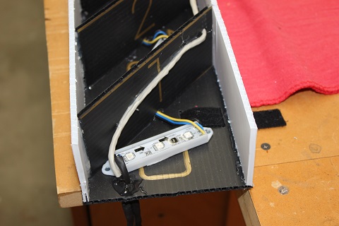
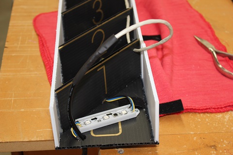
The wiring is complete on this candy cane. TEST TEST TEST... before moving on to putting the tops on. You do not want to get the top on and realize you made a wiring error and have to rip it apart. No .. I didnt have to do that.. but ... with me .. it was a possibility !!
|
WHOA BOB !!! big jump there !!.. Well .. yes .. David at HolidayCoro has a GREAT video on how to assemble the tops. Please go to his site and watch the video. He does a great job in showing how its done.
|
Before we move on with the project let me stop for a minute and tell you about how we decided to connect these up. Originally it was going to be a Cat5 cable from my J1-Sys P2 controller located up on the porch, connecting to a power supply located by the candy canes and the power + signal would be injected into the first candy cane. There would be custom extension cords made from 4-pin waterproof connectors and 18ga 4 wire cable . I built all the extensions (will show later in this How-To) and hooked them all up. They where TERRIBLE!! By the time the power and signal got to the last cane, it was a different color (red was pink) and very dim. I enlisted the help of the good folks from Down Under (AusChrstmaslightlighting.com) and the "showed me the light!!"
Problem was not in the signal. Each pixel regens the signal as close as they are, I didnt need to inject a null pixel. The problem was power. By the time the power reached the end, the voltage drop was down to about 7 volts at the end of the string. So I did some testing,then some more and finally came up the solution of reinjecting a fresh 12V into the string between the 3rd and 4th candy cane, and the 7th and 8th candy cane and at the end of the string. This required building a special "Y" cable (shown later) for not interrupting the signal stream but injecting 12V back into the system. Below I will show what all I did.
Problem was not in the signal. Each pixel regens the signal as close as they are, I didnt need to inject a null pixel. The problem was power. By the time the power reached the end, the voltage drop was down to about 7 volts at the end of the string. So I did some testing,then some more and finally came up the solution of reinjecting a fresh 12V into the string between the 3rd and 4th candy cane, and the 7th and 8th candy cane and at the end of the string. This required building a special "Y" cable (shown later) for not interrupting the signal stream but injecting 12V back into the system. Below I will show what all I did.
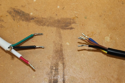
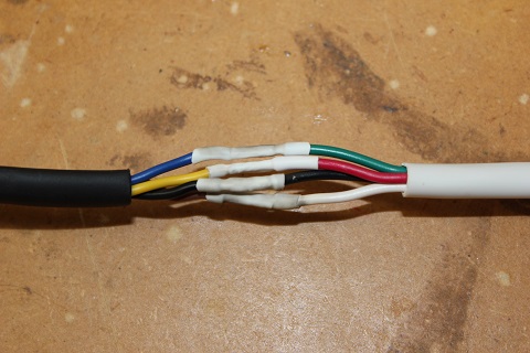
Each of my between the cane extensions are 5' long. This allows me to spread them across the yard for a fuller effect. The power injection cables are varied in length but use the same techniques to build them. I start with the 4-wire cable and the 4-pin connector (YES.. I could have gotten them the same color but the deal was to good to pass up. Besides.. its dark..) and tinned the ends. I then slipped a small piece of heat shrink and pushed it way back out of the way (the white piece on the red wire). ALSO note (you cant really see it) that here is a larger black piece of heat shrink over the black wire. This is cover the whole joint when done.
|
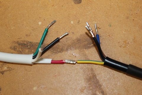
If you have a good iron, you just need to hold the wires side by side and touch them with the iron. I put a little bit of solder on the iron before hand. This make the solder flow fast, gives a good joint and you dont burn your fingers.
|
Let it cool for a second then slip the heat shrink over the joint and use your heat gun (or lighter) to shrink the tube. 1 down, 3 to go.
|
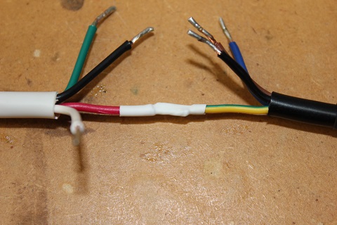
Okay, all 4 wires are soldered and have heat shrink on them. Notice it stays a small bundle.
|
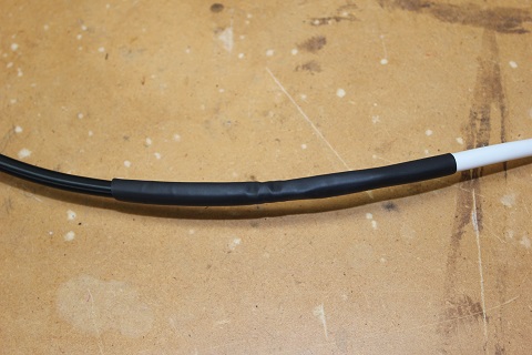
Remember the larger heat shrink from step 1? (you DO remember this .. right? ). Slide it down over the entire joint. Make sure cut a long enough piece so that get good coverage on both ends of the splice.
|
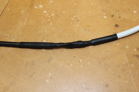
Then shrink it down.
|

Just help out with the weather proofing, I dabbed a little liquid electrical tape around the ends of the heat shrink. Your call.
|
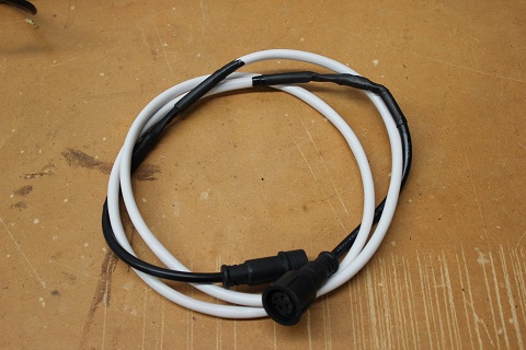
And here we go. The first of many extension cords. These should serve you well in your display.
|
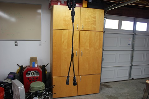
Finally, here is one of the "Y" connectors I made for injecting power along the string. Remember, I have 8 - 16 pixel candy canes using the 3 LED rectangular pixels (WS2811). Total count is 128 pixels. Its going to NEED power.
|
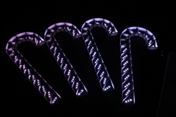
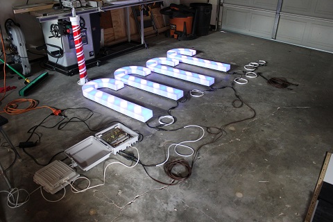
Here is a perfect eample of the power usage. If you enlage the picture and look closely you will notice that the cane on the left is brighter and the color is darker. The last cane (and this is ONLY 4 of the 8) is already showing signs of getting lighter/dimmer.
I didnt expand on the "Y" harness becasue everyone will approach this issue differently. I will explain that I brought another output from the power supply with only 12V on the line. The "Y" harness simply ties and carries on the data signal and the power is just inserted. You do not want to reinject signal, just power (you will mess up the addressing and probably a few pixels along the way.)
I hope this give a good starting point for you if you decide to build your own. As I mentioned earlier these can be as simple or complex as you want to make them. You can buy red and white single color nodes, connect them to a LOR DC card and have canes, You can move on to RGB nodes and DMX controllers or go full bore with the pixels.. Your imagination (and your wallet) are the limit.
Please feel free to contact us if you have any questions on this project. We are more than happy to help if we can. We get so much help from others that it makes us happy to pass along what we learned.
Here is the last part of the project completed. I built the box for the power supply/injector. The idea behind this layout is that the controller box stays up on the porch, high and dry, and I only send the data signal out a CAT5 cable to the power supply located near the display item. Then the power is injected along with the data to power and control the display. Here are some pictures of the completed project.
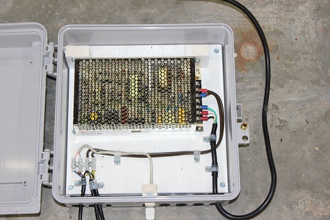
Here is the completed Power Supply box. There is a CAT5 jack in the center, the AC input on the right and the combined (Data + 12VDc) output on the left. The power supply is a 12VDc @ 12.5Amp supply. More than enough power to run the 8 candy canes (128 pixels)
|
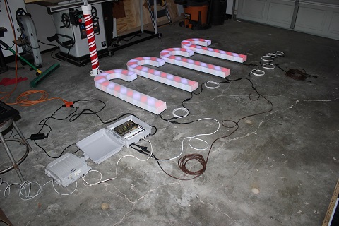
Here is a picture of the whole set up with 4 canes. I was testing the setup and the new power injector cables (the brown Spt2) along with the "Y" injectors.
|
Same pictures just canes a different color. After all, my other photos have 3 on a row. Didnt want this one to look lopsided.
|