DMX Controller Boxes - Pixel and DMX Bridge
In 2012 we decided to break in to DMX control of our display along with our existing Light-O-Rama equipment. We started out by adding 8 of the HolidayCoro Candy Cane Post Toppers (or as we built them, North Pole Toppers). This was a very basic RGB node project that ended up getting alot of comments. We used an E1.31 to DMX brige that we purchased from J1sys.com. I wont go in to trying to explain E1.31 technology. Lets just say that it allows us to use standard ethernet to access and control our DMX devices. Please visit our LINKS page for refrences to our favorite forums. You will find all you ever wanted to know about E1.31 and DMX there.
So in 2012 we threw together a box to hold a small power supply and the DMX bridge. It worked great, but needed to be refined a little after the fray of the 2012 display season was over. Here are the updates we made to our DMX controller boxes.
We now have 3 DMX controllers. One is our E1.31 to DMX bridge for standard DMX control and the other two are our E1.31 to DMX Pixel controllers.
While this is in the How-To section of our website, it is more of a "here is what we did and if you like it, you can do it to" project.
TECH TALK: I wanted a system that was consistent in setup, wiring and configuration which is what brought me to this setup. I wanted to ONLY send data signals out of these boxes (no power) and then inject the pixel/node (smart/dumb) power at the display element. I spoke with the guru's across the forums and got several ideas on suggestions. Using this method, I dont have to use null pixels or pixel extenderes since the distance from the controller to the first pixel is usually less than one foot.
DMX Bridge
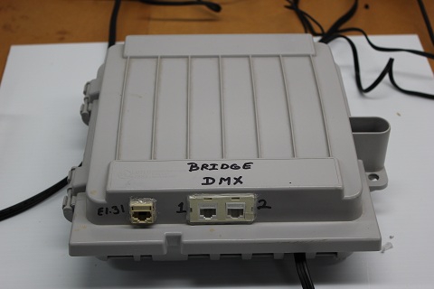
This image shows a CableGuard CG1000 enclosure that I modified by adding RJ45 jacks to the bottom lip of the lid. The jack on the far left is the E1.31 input and the other 2 jacks on the right are the DMX outputs from the J1Sys D2 DMX Bridge.
|

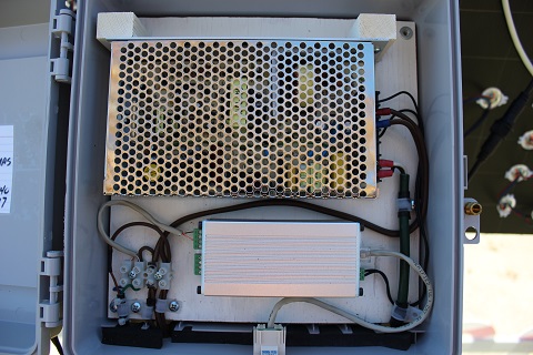
Here you see the box open with the cables from the RJ45 jacks going to the J1Sys D2 Bridge. The modular power supply is a [email protected] amp supply. All is mounted on a thin piece of painted plywood cut to fit. The screws were located from the bottom by screwing in a wood screw then cutting off the top, then pressing the board down leaving location marks for the holes. The entry for the power cord had be opened up to allow the plug to go in without cutting.
|
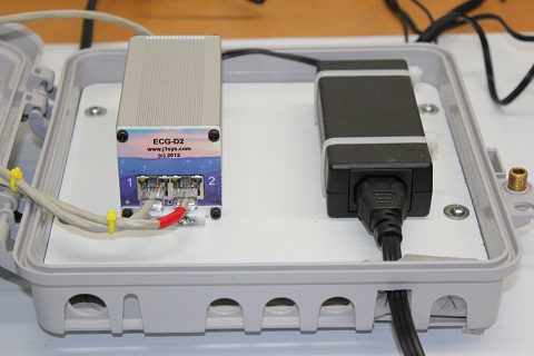
This is just a cioser image of the D2 bridge. I did wire everything in a standard CAT5 configuration (TIA/EIA 568B) and I carry this config all the way through my system. Any built or off the shelf CAT5 cable will always work in my system.
|
E1.31 Pixel Controller - Ver 1
Not used but it works very well
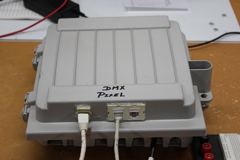
This is basically the exact same layout as the image above. This the controller box for the J1Sys P2 pixel controller. Same layout for the E1.31 input and DMX/SPI output.
|
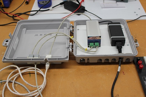
Again, the open view. Note that I did pair off the CAT5 cables. I am running the BROWN pair to P2-Gnd, the BLUE pair to the P2-Clock, the ORANGE pair to the P2-Data, and the GREEN pair to the P2 +V output. Again, any CAT5 cable will work BUT, you must be aware of what and where you plug it in since it does have +12 VDC!!
|
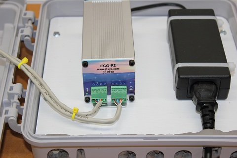
Here is a close up of the P2 with the power supply.
|

Here is the P2 controller on the test bench. I am using the onboard voltage to power the pixels. The power available is not being used to power any prop. The P2 was configured to provide power ONLY to power either pixel extenders or null pixels located between the controller and the prop. This allows for greater cable lengths.
|
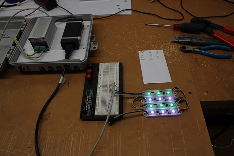
This is simply another view of the test bench setup.
|
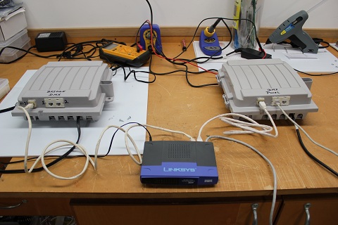
Here I have both controllers connected to the laptop via an ethernet switch. Since E1.31 is ethernet based, a simple switch allows you to controll all of your E1.31 devices from one port on the host computer. I updated the two devices giving them unique IP addresses. Both were managable via the web interface.
|
E1.31 Pixel Controller - Ver 2
Here are a couple of pictures of the E1.31 to SPI (J1Sys P2) controller box mounted on the back of the Merry Christmas sign. We have two of these boxes in the display. The one shown and its twin which runs the PixelCanes and the Leaping Arches.
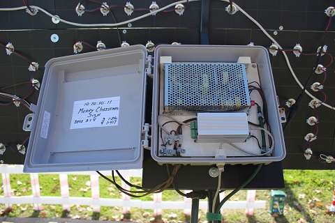
While basically the same concept as the Ver 1 layout, I needed more power supply to run the pixels. This is a CableGuard 1500 series enclosure with a [email protected] power supply and the J1Sys P2 controller mounted on the back of the Merry Christmas sign. The green cord is 110VAC powering the supply, the grey cord is the E1.31 from the switch, the black water proof cord is the main output from the P2 controller carrying 12Vdc and the pixel data. The brown "zip cords" are power taps carrying only 12Vdc for power injection.
|
Just a closer view of the Pixel Controller Box.
|
